What is Atom Sound Renderer (ASR)?
- Atom Sound Renderer (ASR) is a module with three roles:
- 1. Mixing multiple voices
- 2. Effect signal processing
- 3. Audio output to the output destination
- Note
- Although the expression "ASR Rack" is used in the manual and plugin files, "ASR" and "ASR Rack" are basically synonyms.
- The ADX runtime automatically creates an ASR that will be the main output when it is initialized. The method for determining the internal configuration of the main output ASR varies depending on the "mixer operation method" that can be set in CRI AtomCraft.
- (If the mixer operation method is Version 1) Bus settings specified in CRI AtomCraft
- (If the mixer operation method is Version 2 or ACF is not registered) Settings specified in the CriWareInitializer component -> "ASR Rendering Mode"
- Unless otherwise specified, the voice output is sent to the ASR of the main output created by the ADX runtime. The audio sent to the ASR is mixed with the PCM signal, so it is no longer possible to control each individual voice. br>
Voice mixing
- The ASR Rack has its own speaker configuration that it uses for internal rendering. When a voice is sent to the ASR, a conversion is made from the channel configuration of the voice data to the speaker configuration of the ASR.
Speaker Mapping
- Speaker Mapping ( CriWare.CriAtom.SpeakerMapping ) is a value that indicates the speaker configuration used for mixing and rendering audio.
- When the ADX Runtime mixes the input audio data with ASR, it converts it into a format that matches the specified speaker mapping.
If the audio has Panning set, the conversion will be done by panning using Pan speaker type .
- Additionally, signal processing within the Atom sound renderer ( Effect signal processing ) is also performed based on the specified speaker configuration.
- The speaker mapping for the main output ASR can be specified in the "ASR Rendering Mode" item of the CriWareInitializer component when initializing the plugin library. However, if an ACF file is registered, the speaker mapping will be according to the ACF bus settings. When creating a new ASR rack, you can specify the speaker configuration of the mixer to be created in CriWare.CriAtomExAsrRack.Config.speakerMapping.
- Note
- If you do not register an ACF, the default value is CriWare.CriAtom.SpeakerMapping.Auto, which is automatically determined based on the value of CriWare.CriAtomExAsrRack.Config.outputChannels .
For the relationship between CriWare.CriAtomExAsrRack.Config.speakerMapping and CriWare.CriAtomExAsrRack.Config.outputChannels , see Speaker mapping and Number of channels .
- If the channel configuration of the audio data matches the speaker mapping of the mixer, no conversion of the audio data will be performed.
If they do not match, the ADX runtime will downmix (or upmix) the input audio appropriately to match the mixer format.
Pan speaker type
- The pan speaker type is a parameter that determines where panned audio data is rendered.
When you pan an audio signal, the speaker that the audio will be output from is determined by the pan speaker type.
- For example, when you use the CriWare.CriAtomExPlayer.SetPan3dAngle function to position a mono sound behind you (180-degree), if the pan speaker type is 4Ch, the sound will be panned to the Ls and Rs channels.
If the pan speaker type is 6Ch, performing the same operation will pan the audio to the Lb and Rb channels.
- The pan speaker type is automatically set by default.
The resulting speaker output for the panned audio will depend on the speaker mapping you specify for that audio output.
The specific pan speaker types depending on the speaker mapping are:
- For example, if you output mono audio to an ASR created by specifying CriWare.CriAtom.SpeakerMapping.Ch5_1, the pan speaker type will automatically be interpreted as 4Ch and panning will be performed using L, R, Ls, and Rs.
Effect signal processing
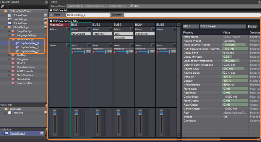
- It is possible to attach the DSP bus settings created with Atom Craft to the ASR.
The DSP bus settings include the ASR bus configuration, bus names, send information between buses, and information about the bus effects on each bus.
- Note
- If no DSP bus settings are attached, such as immediately after creating an ASR Rack, the ASR Rack will have eight buses configured.
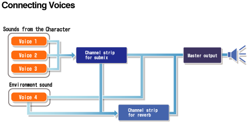
- The voice output to the ASR is sent to the bus via the specified bus send, and is finally output from the 0th bus, MasterOut.
DSP Busses and Effects
- With the ADX, you can freely combine mixers and various effectors using the DSP bus settings to perform advanced sound processing.
How to use DSP bus setting
Creating a DSP bus setup with CRI Atom Craft
- Please refer to the CRI Atom Craft tool manual for instructions on how to create a DSP bus configuration.
Attach the created DSP bus settings to the program.
- Below is the code to attach the DSP bus settings we created.
CriAtomEx.AttachDspBusSetting("DspBusSetting_0");
:
:
criAtomSource.SetBusSendLevelOffset("BUS1", 0.5f);
criAtomSource.Play();
- Generally, you can only attach one DSP bus setting at a time, but In environments where an ASR Rack is available, it can also be attached to the ASR Rack.
CriAtomEx.RegisterAcf(null, "proj.acf");
criAtomExAsrRack.AttachDspBusSetting("DspBusSetting_0");
:
:
criAtomSource.player.SetAsrRackId(rackId);
criAtomSource.SetBusSendLevelOffset("BUS1", 0.5f);
criAtomSource.Play();
Custom Effect Plugin
- In addition to the standard CRI effects, ADX audio effects can also include user-created or third-party effects that can be used as plug-ins.
- By creating an effect plug-in created with the CRI ADX Audio Effect Plug-in SDK as a VST, it becomes easier to adjust parameters on the tool. CRI ADX Audio Effect Plugin SDKFor more information, please refer to the related items in the CRI Atom Craft tool manual.
Mixer AISAC
- The Mixer AISAC is an AISAC that can be configured for DSP Bus Settings.
Just like a normal AISAC, you can change the parameters of the DSP bus using the AISAC control value.
The following bus parameters can be controlled via the mixer AISAC:
- Volume
- Pan Angle
- Bus Send Level
- Pan spread
- The AISAC mixer has the following different specifications compared to the standard AISAC.
- AISAC control values cannot be operated from other AISACs.
The AISAC control value is controlled by CriWare.CriAtomExAsrRack.SetAisacControl.
- AISAC modulation is not available.
- It is not possible to attach a new mixer AISAC at runtime.
- For information on how to configure on CRI Atom Craft, please refer to the CRI Atom Craft tool manual.
3rd Party Effects
- ADX has the ability to work in conjunction with 3rd party effects in addition to ADX built-in effects.
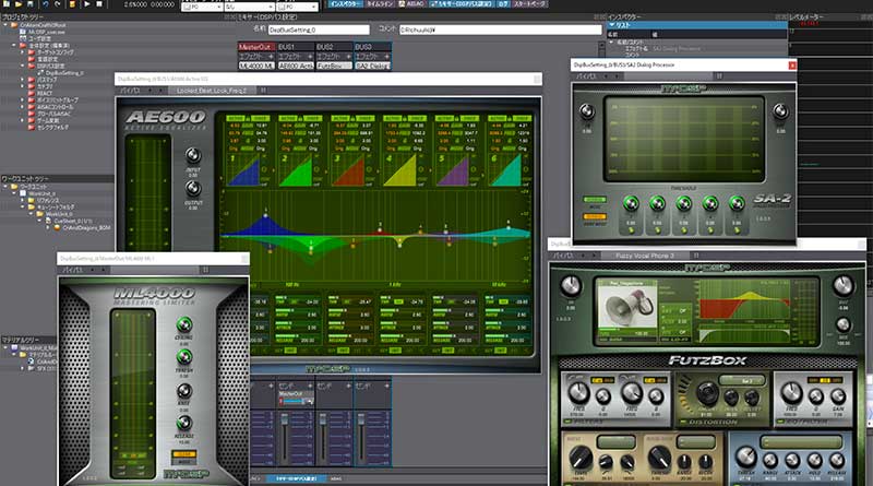
McDSP Effects
- It handles the ADX function expansion CRI ADX Audio Effect McDSP Expansion, which allows McDSP effects to be incorporated into the ADX .
You can try out McDSP effect plug-ins that can be integrated into CRI Atom Craft for free for one month.
-
- For information on how to incorporate the McDSP plug-in, please refer to the documentation located in the following directory of the SDK.
/cri/expansion/cri_audio_effect/
output to a destination
ASR sound output type
- The output destination of the ASR output bus is determined according to the DSP bus setting included in the ACF. If you do not attach a DSP bus setting, you can also specify it by setting the following value to CriWare.CriAtomExAsrRack.Config.soundRendererType.
- If CriWare.CriAtomEx.SoundRendererType.Asr is specified, sound will be output to another ASR specified in CriWare.CriAtomExAsrRack.Config.outputRackId.
Therefore, it cannot be specified for the ASR created when the plugin library is initialized.
If you specify CriWare.CriAtomEx.SoundRendererType.Spatial , the 3D sound function will be enabled inside the ADX .
For more information about the spatial audio feature, see Stereophonic sound .
Number of ASR output channels
- When creating an ASR, you can specify the speaker mapping and output channel. These two parameters have the following meanings:
Speaker mapping and Number of channels
- The speaker mapping default is CriWare.CriAtom.SpeakerMapping.Auto, which is automatically determined based on the output Number of channels value. Therefore, in many cases, you can get the correct results by specifying only CriWare.CriAtomExAsrRack.Config.outputChannels.
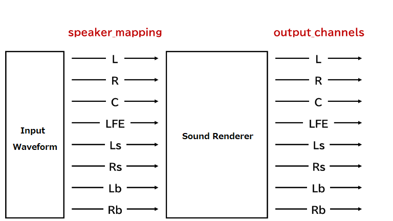
The diagram below shows the flow when playing 7.1 ch audio material with ASR set to CriWare.CriAtomExAsrRack.Config.outputChannels = 8 .
CriWare.CriAtomExAsrRack.Config.speakerMapping will automatically be set to CriWare.CriAtom.SpeakerMapping.Ch7_1, and the ASR will operate with 8 channels and output directly to the platform.
Number of channels and platform
- It is possible to specify a Number of channels that exceeds the Number of channels supported by the platform.
At that point, the ADX runtime will determine the maximum Number of channels supported by the platform and perform an additional downmix on the ASR output.
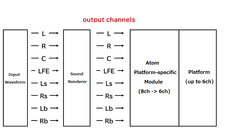
The following diagram shows the flow when CriWare.CriAtomExAsrRack.Config.outputChannels is set to 8 for a platform that supports up to 5.1ch.
The ASR operates at 8ch, but the output is downmixed to 6ch by Atom's platform-specific module and output to the platform.
- Attention
- When the value of CriWare.CriAtomExAsrRack.Config.outputChannels is equal to or greater than the maximum Number of channels for the platform, the ASR sends a signal with that maximum Number of channels to the platform.
At this time, some platforms may perform further conversion from the signal with the maximum number of Number of channels received to match the Number of channels of the actual device. This process is platform-specific and has nothing to do with downmixing in Atom.
- Note
- The default value of CriWare.CriAtomExAsrRack.Config.outputChannels for ASR in ADX Runtime for smartphones is 2.
If you want to see the same output on your PC, set CriWare.CriAtomExAsrRack.Config.outputChannels to 2 to get consistent stereo sound output across various platforms.
Downmix formula
- Downmixing may occur within an Atom when the following values are different:
- Downmixing in Atom follows the formula in the table below.
| Number of input channels | Number of output channels | Formula (output speakers) = (input speakers) |
| 7.1.4.4ch | 7.1.4ch | L(mix) = L + Lbf * (-3dB)
R(mix) = R + Rbf * (-3dB)
C(mix) = C
LFE(mix) = LFE
Ls(mix) = Ls
Rs(mix) = Rs
Lb(mix) = Lb + Lbb * (-3dB)
Rb(mix) = Rb + Rbb * (-3dB)
Ltf(mix) = Ltf
Rtf(mix) = Rtf
Ltb(mix) = Ltb
Rtb(mix) = Rtb
|
| 7.1.4ch | 7.1ch | L(mix) = L + Ltf * (-3dB)
R(mix) = R + Rtf * (-3dB)
C(mix) = C
LFE(mix) = LFE
Ls(mix) = Ls
Rs(mix) = Rs
Lb(mix) = Lb + Ltb * (-3dB)
Rb(mix) = Rb + Rtb * (-3dB)
|
| 7.1ch | 5.1ch | L(mix) = L
R(mix) = R
C(mix) = C
LFE(mix) = LFE
Ls(mix) = Ls + Lb * (-3dB)
Rs(mix) = Rs + Rb * (-3dB) |
| 5.1ch | 4ch(L,R,Ls,Rs) | L(mix) = L + C * (-3dB)
R(mix) = R + C * (-3dB)
Ls(mix) = Ls
Rs(mix) = Rs |
| 4ch(L,R,Ls,Rs) | 2ch | L(mix) = L + Ls * (-3dB)
R(mix) = R + Rs * (-3dB) |
| 2ch | 1ch | MONO(mix) = L * (-3dB) + R * (-3dB) |
- For combinations not listed in the table above, the audio will be downmixed in stages.
For example, if the input is 7.1ch -> output is 2ch, it will be downmixed in the following order: 7.1ch -> 5.1ch -> 4ch -> 2ch.
As a result, the downmix formula becomes:
L(mix) = L + C * (-3dB) + Ls * (-3dB) + Lb * (-6dB)
R(mix) = R + C * (-3dB) + Rs * (-3dB) + Rb * (-6dB)
THIS SERVICE MAY CONTAIN TRANSLATIONS POWERED BY GOOGLE. GOOGLE DISCLAIMS ALL WARRANTIES RELATED TO THE TRANSLATIONS, EXPRESS OR IMPLIED, INCLUDING ANY WARRANTIES OF ACCURACY, RELIABILITY, AND ANY IMPLIED WARRANTIES OF MERCHANTABILITY, FITNESS FOR A PARTICULAR PURPOSE AND NONINFRINGEMENT.